Icosahedron — subdividing and mapping

ChatGPT helped me increase the number of sides on an Icosahedron .obj I downloaded.

It’s not doing great at eliminating this distortion in the texture mapping though:

This is the code it’s using:


function generateUVs(positions)
    local uvs = {}
    for _, pos in ipairs(positions) do
        local normalizedPos = pos:normalize()
        
        -- Compute theta and phi
        local theta = math.atan(normalizedPos.z, normalizedPos.x)
        local phi = math.acos(normalizedPos.y)
        
        -- Convert to UV coordinates
        local u = (theta + math.pi) / (2 * math.pi)
        local v = phi / math.pi
        
        table.insert(uvs, vec2(u, v))
    end
    return uvs
end

… can anyone see what mistake it’s making?

Here’s the project:
Icosahedron Mapping.zip (3.0 MB)

@UberGoober - not sure if this will help but we encountered a similar problem with spheres and after many posts was resolved. Try the following link.

Distorted wrapping

@Bri_G i appreciate the tip, and am I missing something? This post looks like he concludes there’s no good way to do the texture mapping at all…

@UberGoober See my Earth program on WebRepo. I ran into the jagged edge when I first started to write code to wrap a rectangular image onto a sphere.

The only way i managed to get the texture to wrap correctly on a sphere was to use PseudoMesh class from @LoopSpace (it is in the code i shared for the 3d ray tracing with raycast stuff).

I know that I’ve explained this elsewhere on this forum, but I guess that stuff like this gets buried in discussions and is hard to find. Maybe I should do a blog post … in my copious free time!

You can’t assign a consistent texture coordinate to a position vector on a sphere. The texture coordinate depends on which triangle the position vector belongs to. For simplicity, let’s assume that we’re talking about a sphere representing the earth and we want to wrap the texture horizontally around the sphere so that the 0th meridian (through Greenwich) is the seam. We want to wrap it so that Europe (or at least, the majority of it) has negative u coordinate whilst the Americas have positive u coordinate.

Any vector on the meridian, therefore, could belong to a triangle that is along the left-hand edge of the texture if it juts into Europe, in which case it should have u coordinate -1, or along the right-hand edge of the texture if it points towards the Americas and so should have u coordinate of 1.

The same thing, incidentally, happens with cylinders and might be easier to visualise if you envision wrapping a label around a can.

This also means that you have to be careful in your choice of model when wanting to use a sphere with a texture since if you don’t have a clear seam then picking the right texture coordinates can be a nightmare. I’ve nearly always used my own models (since I know how they were built) so I don’t know if the standard sphere in Codea suffers from this issue. In short, without a clear seam then you have triangles that don’t know which end of the texture they should belong to and you need to have an overlapping edge on the texture where a strip from the left-hand edge is repeated on the right. Simpler just to have a seam.

There’s a similar issue at the poles where you should also ensure that the texture coordinate of a vertex at the pole depends on the triangle, but this is a bit easier to fluff - especially if your texture is monochrome near the top and bottom edges (such as the earth … at least, for the time being).

Found it: Craft sphere texture - #57 by LoopSpace

@LoopSpace I didn’t see a link where I could download your mapped sphere, did I miss it or was it somewhere else?

@dave1707 your Earth is fantastic but it’s using an icosphere not an icosahedron. If you download the zip from the first post you can see the obj for the icosahedron that I’m using.

I’m using an icosahedron because I’m trying to convert the pheromone code from @Jmv38’s ants project into 3D, and because icosahedron have equidistant vertices it will presumably make it a little easier to figure out how to plot and detect the pheromones….

@UberGoober Sorry, I wasn’t paying much attention to the name icosahedron.

But I did run into the jagged edge when I was doing the icosphere. It’s been awhile, but I think I had to find a seam and work from there.

@UberGoober - thinking about this thread - I’m sure you can texture an icosahedron by calculation but I’m sure it will take a lot of fine tuning to achieve a smooth textured model with no flaws.

What I have done in the past is use an obj model in Blender and export the texture shape to a graphics package to add the detail I needed.

Then all you need to do is load the model in Codea.

Edit: another package to do this is Wings3D.

@UberGoober My mesh code (which includes many shapes) can be found at https://github.com/loopspace/Codea-Library-Graphics/blob/master/MeshExt.lua, with my PseudoMesh class (https://github.com/loopspace/Codea-Library-Graphics/blob/master/PseudoMesh.lua) then this can be exported to a model suitable for use with Craft.

I think that there’s some standalone code that starts with Craft’s sphere and modifies it to produce a textured sphere. This is in the thread I linked above (a bit higher up than the linked post).

@UberGoober @Bri_G Do either of you have a complete program that uses the pseudomesh code to texture a sphere. I guess I’m being lazy and just want to install and run some code without having to search for all the pieces and put them together.

@dave1707 - maybe, I’ll dig around but I think I moved away from the meshing and used a sphere obj model when I needed it. I tried the pseudomesh that @LoopSpace introduced. I seem to remember someone using it for an aquatic simulation in sea bottom sim related to their work.

I’ll dig around and see if I can find it.

@dave1707 here is a simple example using the pseudoMesh() class
You need to add pseudomesh and orbitviewer as dependences.

@Bri_G yes it was me that did the deep sea neutrino telescope simulation

-- PseudoMeshSphere

function setup()
    scene = craft.scene()
    
    scene.camera:add(OrbitViewer,vec3(0,0,0),50,0,1000)     
        
    sphereMesh = PseudoMesh()   
    sphereMesh:addSphere({
--            axis=vec3(0,1,0),
            size=3,
            centre=vec3(0,0,0)
        })
    
    sphereModel= sphereMesh:toModel()   
    
    mySphere=scene:entity()
    mySphere.model=sphereModel
    mySphere.material= craft.material(asset.builtin.Materials.Standard)
    mySphere.material.map = readImage(asset.builtin.Surfaces.Basic_Bricks_Color)
end

function update(dt)
    scene:update(dt)
end

-- This function gets called once every frame
function draw()
    update(DeltaTime)
    scene:draw()
end

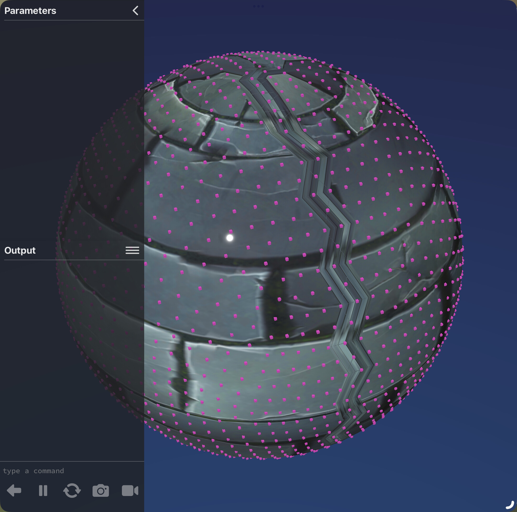
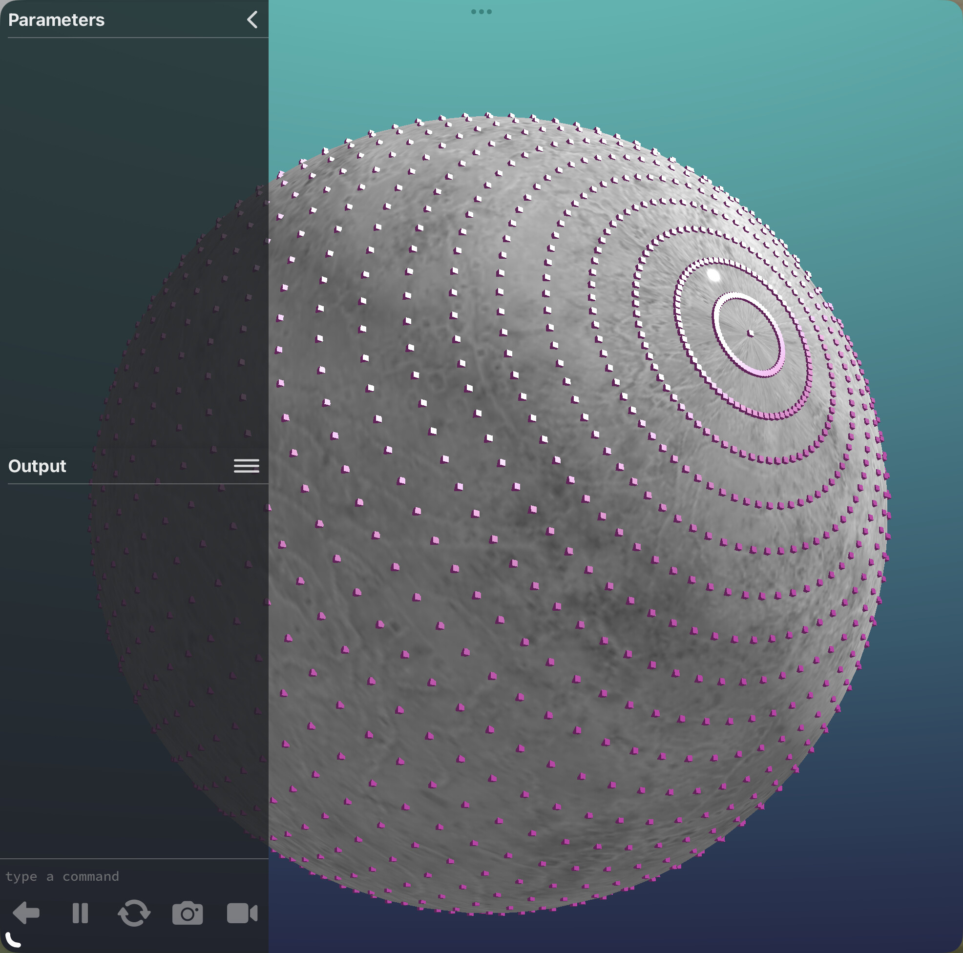
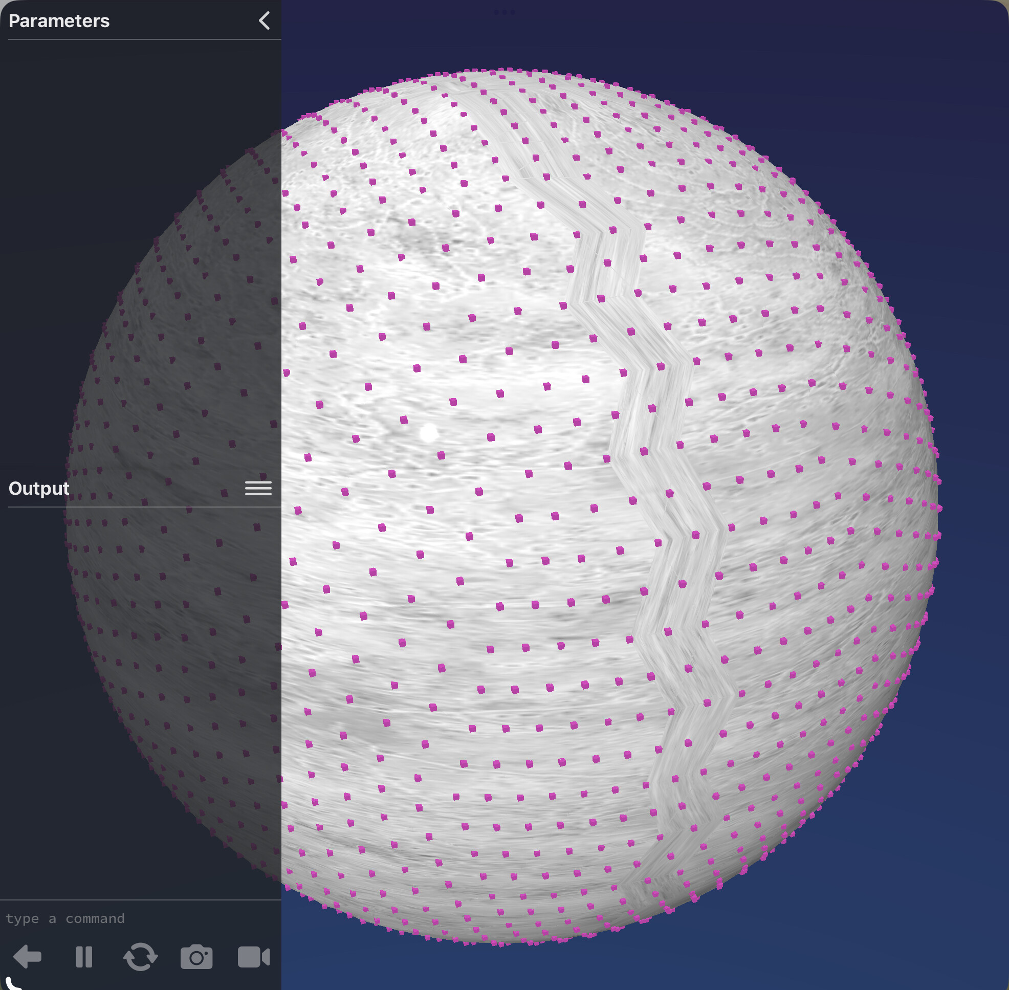
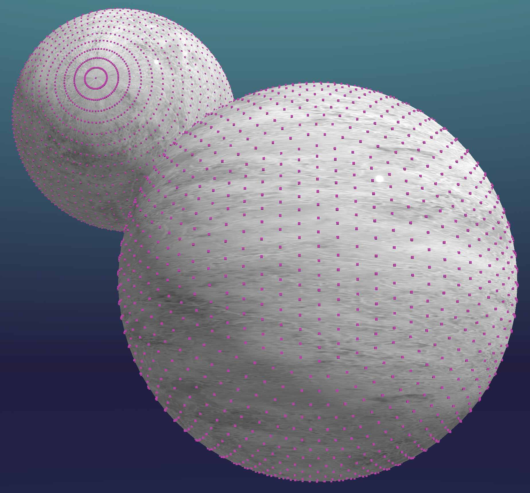
@UberGoober @dave1707 - here is an approach for textured spheres/icosahedron which uses a shader. Written by @Muffincoder which allows reduction of sides and panels. It may help translate vertices to texture maps as the top and bottom of the sphere are well defined

function setup()
    --
    --[[  Sphere generator v1
        This is an app made in Codea written by Muffincoder on Codeas' forum
        You may use this code for whatever you like, I would be glad to see
        whatever you come up with using this or use this for.
        Also note that the algorithm I came up with is not optimal, it works, that's it.
        If you improve the algorithm then please tell me what and how you did it.
        This was purely a fun project that I created on my pastime. Enjoy!
    ]]
    -- Definitions of the amount of fragments vertically and horizontally
    segmentsH = 100
    segmentsV = 30
    size = 100    -- The radius of the sphere
    -- This is the texture for the sphere, use a rectangular texture for example an image of earth.
    texture = "Documents:earth"
    -- Also note that the sphere can be either colored with random colors or textured
    -- This is made possible with the use of 2 shaders, one for pure color and one basic texture shader
    colorOnlyShader = shader([[
    uniform mat4 modelViewProjection;
    attribute vec4 position;
    attribute vec4 color;
    varying lowp vec4 vColor;
    void main()
    {
        vColor = color;
        gl_Position = modelViewProjection * position;
    }

        ]],[[
    precision highp float;

    varying lowp vec4 vColor;

    void main()
    {
        gl_FragColor = vColor;
    }
        ]])
        textureShader = shader([[
    uniform mat4 modelViewProjection;
    attribute vec4 position;
    attribute vec4 color;
    attribute vec2 texCoord;
    varying lowp vec4 vColor;
    varying highp vec2 vTexCoord;
    void main()
    {
        vColor = color;
        vTexCoord = texCoord;
        gl_Position = modelViewProjection * position;
    }
    ]],[[
    precision highp float;
    uniform lowp sampler2D texture;
    varying lowp vec4 vColor;
    varying lowp vec2 vTexCoord;
    void main()
    {
        lowp vec4 col = texture2D(texture, vTexCoord) * vColor;
        gl_FragColor = col;
    }
    ]])

    -- Variable init
    meshS = mesh()
    verts = {}
    vertices = {}
    colors = {}
    texels = {}
    texCoords = {}

    parameter.integer("segmentsH",5,150,segmentsH)
    parameter.integer("segmentsV",3,150,segmentsV)
    parameter.action("generateSphere",generateSphere)
    parameter.boolean("randomColors",true)
    parameter.integer("dist",-1000,0,-350)
    parameter.integer("rotX",0,360,0)
    parameter.integer("rotY",0,360,0)
    parameter.integer("rotZ",0,360,0)

    generateSphere()
end

function generateSphere()
    --
    -- Calculate how big of an angle each fragment of the sphere has
    local segmentHangle = (2*math.pi)/segmentsH
    local segmentVangle = (math.pi/(segmentsV+1))
    -- Reset arrays if set already, or initialize them if this is the first run
    meshS = mesh()
    verts = {}
    vertices = {}
    colors = {}
    texels = {}
    texCoords = {}

    --First part is to generate each unique vertex for the sphere
    --Starting with the topmost vertex
    table.insert(verts,vec3(0,size,0))
    table.insert(texels,vec2(0.5,1.0))

    for i=1,segmentsV do
        local texelY = 1-(i / segmentsV)*((segmentsV-1)/segmentsV)
        for j=1,segmentsH do
            --Radius parameter exposed for easier manipulation of the surface
            -- you can for example add some noise here to make the surface 'grainy'
            local length = size
            local posX = math.cos(j*segmentHangle)*length*math.cos(math.pi/2 + (i*segmentVangle))
            local posZ = math.sin(j*segmentHangle)*length*math.cos(math.pi/2 + (i*segmentVangle))
            local posY = math.sin(math.pi/2 + (i*segmentVangle))*length
            local texelX = 1-(j / segmentsH)
            table.insert(verts,vec3(posX,posY,posZ))
            table.insert(texels,vec2(texelX,texelY))
        end

    end

    -- And ending with the bottom vertex
    table.insert(verts,vec3(0,-size,0))
    table.insert(texels,vec2(0.5,0.0))
    print("Nr of unique vertices: "..#verts)
    print("Nr of unique texels: "..#texels)

    -- Then generate the mesh out of the unique vertices
    for i=1,#verts do
        --[[I split the sphere into 3 parts;
         A Top part, a middle part and a bottom part.
          -The top and bottom ones are pretty much the same but the latter turned upside down.
          -The top vertex and the first ring of vertices assemble a circle using
           triangles that all share the top vertex. The same for the bottom part.
          -The middle part is just a mesh of the remaining vertices
        ]]

        -- Top part
        if i == 1 then
            for j=1,segmentsH-1 do
                local curIndex = i + j
                table.insert(vertices,verts[i])
                table.insert(vertices,verts[curIndex+1])
                table.insert(vertices,verts[curIndex])

                table.insert(texCoords,texels[i])
                table.insert(texCoords,texels[curIndex+1])
                table.insert(texCoords,texels[curIndex])
            end

            table.insert(vertices,verts[i])
            table.insert(vertices,verts[i+1])
            table.insert(vertices,verts[i+segmentsH])

            table.insert(texCoords,texels[i])
            table.insert(texCoords,texels[i+1])
            table.insert(texCoords,vec2(1.0,texels[i+segmentsH].y))
            i = i + segmentsH 

        -- Middle part
        elseif i > segmentsH and i < #verts then
            local lastRow = i - segmentsH
            local thisRow = ((i-1) % segmentsH)+1
            if lastRow > 1 then
                table.insert(vertices,verts[i])
                table.insert(vertices,verts[lastRow+1])
                table.insert(vertices,verts[lastRow])
                if thisRow == 1 then
                    table.insert(texCoords,vec2(1.0,texels[i].y))
                    table.insert(texCoords,texels[lastRow+1])
                    table.insert(texCoords,vec2(1.0,texels[lastRow].y))
                else
                    table.insert(texCoords,texels[i])
                    table.insert(texCoords,texels[lastRow+1])
                    table.insert(texCoords,texels[lastRow])
                end
            end

            if i+1 < #verts then
                table.insert(vertices,verts[i])
                table.insert(vertices,verts[i+1])
                table.insert(vertices,verts[lastRow+1])
                if thisRow == 1 then
                    --table.insert(texCoords,vec2(1.0,texels[lastRow].y))
                    table.insert(texCoords,vec2(1.0,texels[i].y))
                    table.insert(texCoords,texels[i+1])
                    table.insert(texCoords,texels[lastRow+1])
                else
                    table.insert(texCoords,texels[i])
                    table.insert(texCoords,texels[i+1])
                    table.insert(texCoords,texels[lastRow+1])
                end
            end
            -- Bottom part
            if i == (#verts-segmentsH) then
                for j=1,segmentsH-1 do
                    local curIndex2 = i + j
                    table.insert(vertices,verts[#verts])
                    table.insert(vertices,verts[curIndex2])
                    table.insert(vertices,verts[curIndex2-1])
                    table.insert(texCoords,texels[#verts])
                    table.insert(texCoords,texels[curIndex2])
                    table.insert(texCoords,texels[curIndex2-1])
                end
                table.insert(vertices,verts[#verts])
                table.insert(vertices,verts[#verts-1])
                table.insert(vertices,verts[#verts-segmentsH])
                table.insert(texCoords,texels[#verts])
                table.insert(texCoords,vec2(1.0,texels[#verts-1].y))
                table.insert(texCoords,texels[#verts-segmentsH])
                i = i + segmentsH
            end
        end
    end

    meshS.vertices = vertices
    meshS.texCoords = texCoords

    if randomColors then
        for i=1,#vertices,3 do-- Color each triangle with a different color
            randomCol(3)
        end
        meshS.colors = colors
        meshS.shader = colorOnlyShader
        meshS.texture = ""
    else
        meshS:setColors(255,255,255,255)
        meshS.texture = texture
        meshS.shader = textureShader
    end

    print("Final mesh vertex count: "..#vertices)
    print("Color array length: "..#colors)
    print("Tex-coord array length: "..#texCoords)
    print("---------")
end

function draw()
    --
    background(0, 0, 0, 255)
    fill(255, 255, 255, 255)
    camera(0,0,5, 0,0,0, 0,1,0)  -- Camera setup
    perspective(45,WIDTH/HEIGHT,0.1,10000)
    translate(0,0,dist)          -- Translate the sphere a bit into the screen
    rotate(rotX,1,0,0)           -- And rotate the object 
    rotate(rotY+ElapsedTime*10,0,1,0)
    rotate(rotZ,0,0,1)
    meshS:draw()                 -- Draw sphere
end

function randomCol(n)
    local col = vec4(math.random(),math.random(),math.random(),1.0)
    for q=1,n do
        table.insert(colors,col)
    end
end

Here’s something I wrote a long time ago that’s kind of similar.

function setup()
    parameter.number("view",1,10,3)
    parameter.integer("level",2,200,12)
    parameter.action("new sphere",setup1)
    parameter.number("AngleX",0,360,90)
    parameter.number("AngleY",0,360,140) 
    parameter.number("AngleZ",0,360,90)
    setup1()
end

function setup1()    
    tab={}  -- table of points
    r=10    -- radius of sphere
    M=level
    N=level
    for n=0,N do
        tab[n]={}
        for m=0,M do
            -- calculate the x,y,z point position
            x=r * math.sin(math.pi * m/M) * math.cos(2*math.pi * n/N)
            y=r * math.sin(math.pi * m/M) * math.sin(2*math.pi * n/N)
            z=r * math.cos(math.pi * m/M)
            -- 2 dimension table of sphere points
            tab[n][m]=vec3(x,y,z)
        end
    end
    sph={}
    for n=0,N-1 do
        for m=0,M-1 do
            -- loop thru sphere table to create a rectangle
            -- create 2 triangles from 4 points of a rectangle
            -- create 1st triangle of the rectangle
            table.insert(sph,tab[n][m])
            table.insert(sph,tab[n][m+1])
            table.insert(sph,tab[n+1][m+1])  
            -- create 2nd triangle of a rectangle        
            table.insert(sph,tab[n][m])
            table.insert(sph,tab[n+1][m])
            table.insert(sph,tab[n+1][m+1])
        end
    end
    -- create table of random colors for each triangle
    cols={}
    for z=1,#sph,6 do
        col=vec4(math.random(),math.random(),math.random(),1)
        for q=1,6 do
            table.insert(cols,col)
        end
    end
    -- create mesh
    sphere=mesh()
    sphere.vertices=sph
    sphere.colors=cols      
end

function draw()  
    background(40, 40, 50)
    perspective(view/2,WIDTH/HEIGHT)
    camera(2000,0,0,0,0,0,0,1,0)
    rotate(AngleX,1,0,0)
    rotate(AngleY,0,1,0)
    rotate(AngleZ,0,0,1)
    sphere:draw()
end

The PseudoMesh texture mapping is indeed very nice.

And as far as I can tell, these aren’t simple to convert for use with icosahedron, and icosahedron (with faces subdivided several times) being a lot more like a geodesic dome.

Here’s the PseudoMesh sphere, with pink cubes put at each of its vertices:

…the sphere being made of vertices that are farther apart at the equator and closer together at the poles…

…and here’s the icosahedron obj, with pink cubes at each of its vertices:

…the icosahedron being made of triangles with all vertices nearly equidistant from all others.

I’ve updated the example project to show both spheres:

Icosahedron Mapping.zip (2.2 MB)

@piinthesky Thanks for the code. I added the dependencies and everything ran ok.

@UberGoober Here’s a stripped down version of my sphere texture program. I added code to draw small spheres at the vertice points. So this code not only doesn’t have the jagged edge, it also has the vertice points at equal distance at the poles like the icosahedron.

viewer.mode=FULLSCREEN

function setup()  
    -- create test texture
    myImg=image(1024,512)
    setContext(myImg)
    background(0, 238, 255)
    fill(0, 19, 255, 255)
    text("abcdefghijklmnopqrstuvwxyzabcdefghijklmnopqrstuvwxyzabcdefghijklmnopqrstuvwxyzabcde",512,490)
    text("abcdefghijklmnopqrstuvwxyzabcdefghijklmnopqrstuvwxyzabcdefghijklmnopqrstuvwxyzabcde",512,22)
    fontSize(40)
    text("abcdefghijklmnopqrstuvwxyzabcdefghijklmnopqrstuvwxyz",512,512*.8)
    text("abcdefghijklmnopqrstuvwxyzabcdefghijklmnopqrstuvwxyz",512,512*.65)
    text("abcdefghijklmnopqrstuvwxyzabcdefghijklmnopqrstuvwxyz",512,512*.5)
    text("abcdefghijklmnopqrstuvwxyzabcdefghijklmnopqrstuvwxyz",512,512*.35)
    text("abcdefghijklmnopqrstuvwxyzabcdefghijklmnopqrstuvwxyz",512,512*.2)
    stroke(0)
    strokeWidth(2)
    for z=0,1024,64 do
        line(z,0,z,512)
    end
    for z=0,512,32 do
        line(0,z,1024,z)
    end
    setContext() 
    -- end test texture 
    
    assert(OrbitViewer, "Please include Cameras as a dependency")
    scene = craft.scene()
    v=scene.camera:add(OrbitViewer, vec3(0,0,0), 1000, 0, 3000)
    scene.ambientColor=color(255)
    
    s1=createSphere(vec3(0,0,0),200,4,myImg)
    
    for a,b in pairs(s1.model.positions) do 
        smallSpheres(b)
    end
end    

function smallSpheres(p)    -- draw spheres at the vertices points
    local pt=scene:entity()
    pt.position=vec3(p.x,p.y,p.z)
    pt.model = craft.model.icosphere(2,1)
    pt.material = craft.material(asset.builtin.Materials.Basic)
    pt.material.diffuse=color(255,0,0)
end

function draw()
    update(DeltaTime)
    scene:draw()
    sprite(myImg,WIDTH-200,100,300)
    s1.rotation = quat.eulerAngles(-90,0,0)
end

function update(dt)
    scene:update(dt)
end

function createSphere(pos,size,level,image)
    local s=scene:entity()
    s.position=vec3(0,0,0)
    s.model = craft.model.icosphere(size,level)
    s.material = craft.material(asset.builtin.Materials.Standard) 
    icoTexture(s,image)
    return s
end

function icoTexture(sph,img)
    local seam=0
    local ax,bx,cx,ay,by,cy,c,lat,lon  
    local posTab={}   --sph.model.positions
    local pTab,cTab,nTab,llTab,uvTab,colTab,norTab,iTab={},{},{},{},{},{},{},{}
    local deg=math.deg
    local asin=math.asin
    local atan=math.atan
    sph.material.map=img 
    
    -- create tables for rounded icospheres        
    iTab=sph.model.indices
    pTab=sph.model.positions
    cTab=sph.model.colors
    nTab=sph.model.normals  
    for a,b in pairs(iTab) do
        posTab[a]=pTab[b]
        colTab[a]=cTab[b]
        norTab[a]=nTab[b]
        iTab[a]=a
    end
    
    -- convert sphere positions to latitude and longitude
    for a,b in pairs(posTab) do
        c=b:normalize()
        lat=deg(asin(c.z))+90
        lon=deg(atan(c.y,c.x))
        llTab[a]=vec2(lon,lat)      -- save lon, lat in table
        if lon//1==-149 then        -- get exact value of seam
            seam=lon
        end
    end 
    
    -- shift points on the left side of the seam to the right side 
    for a,b in pairs(llTab) do        
        b.x=b.x-seam
        if b.x<-.01 then
            b.x=b.x+360
        end
    end 
    
    -- shift individual points of triangle if needed, elimates jagged edge  
    for z=1,#llTab,3 do
        ax,ay=llTab[z].x,llTab[z].y
        bx,by=llTab[z+1].x,llTab[z+1].y
        cx,cy=llTab[z+2].x,llTab[z+2].y
        if ax>250 or bx>250 or cx>250 then
            if ax<.01 then 
                ax=360
            end
            if bx<.01 then
                bx=360
            end
            if cx<.01 then
                cx=360
            end  
        end  
        if ay==0 or ay==180 then
            ax=(bx+cx)*.5
        elseif by==0 or by==180 then
            bx=(ax+cx)*.5
        elseif cy==0 or cy==180 then
            cx=(ax+bx)*.5
        end  
        
        -- create uv table
        uvTab[z]=vec2(ax/360,ay/180)
        uvTab[z+1]=vec2(bx/360,by/180)
        uvTab[z+2]=vec2(cx/360,cy/180)
    end 
    
    -- update tables 
    sph.model.uvs=uvTab
    sph.model.indices=iTab
    sph.model.positions=posTab
    sph.model.colors=colTab
    sph.model.normals=norTab
end