Made some progress-now handles arbitrary number of objects, shapes, rays, with reflection, internal reflection, refraction…
A tribute to Pink Floyd- implemented chromatic dispersion (refractive index depends on wavelength).

I would like to be able to move objects in the 3d space using the touch. I think to move the objects in the plane of the screen keeping the ‘z-distance’ of the object from the screen fixed. But I need to take into account that the world coordinate system can be rotated by prior use of orbitviewer. Anyone (@dave1707 , @John,…) know how to convert a screen touch deltax, deltay to a world.deltax,deltay,deltaz given the orbitviewer rotation?
@piinthesky You can use the camera:screenToWorld() function. You give it a position on the screen and a depth value (as a vec3) and it will give you the world space position of that corresponding point
    local screenPoint = vec3(touch.x, touch.y, 5) -- this gives you a point 5 meters into the screen
    local worldPoint = scene.camera:get(craft.camera):screenToWorld(screenPoint)
Hope that helps
Thanks @John that worked a treat…

1 Like
I just happened to be struggling with raycasting when I saw this post come up, is it okay if I piggyback with a question here?
I have an old project that lets you play around with all the models in Codea’s 3D library, called LivePositioner, all based on Codea’s parameter controls.
LivePositioner Touch.zip (152.2 KB)
I want to implement some touch controls but I am having trouble getting raycasting to work, mainly because I have no way to tell where or what size the rigidbodies actually are.
I tried to make a blanket of “snowfall” to reveal the rigidbody positions but it ended up not telling me much.
it seems like @John is saying rigidbodies won’t scale non-uniformly, and my project lets you scale the x, y, and z dimensions of every model separately, so I guess I’m just out of luck re: rigidbodies?
If you assigned a rigid body to each model (self.entity:add (craft.shape.model, self.entity.model). The rigid body will have the same size as the model. Then use scene.physics:raycast to select the object directly in front of the touch position. If you do an entity.scale=vec3(1,1,1)*scalefactor everything should work. If you make the scaling asymmetric it won’t work.
@dave1707 can you change the title of this thread to ‘3D ray tracing using raycast’. I didn’t figure out how to change the title.
Yeah my whole thing is based on being able to scale the models any way you like on each axis independently…
I think there’s nothing for it but to figure out how to do it with model bounds.
Also I think using craft.shape.model is supposed to be a drag on the system if there are too many models and they’re too complex, and LivePositioner uses a lot of models of varying complexity, like the boats and the spaceships in the default asset packs—but I’m sure I could be wrong about that, too, that’s just my impression.
Aren’t you only using the raycast to select the model. I doubt it matters very much if the rigid model does not match exactly the rendered model. If the touch is near the centre it should be okay?
If it is really an issue, I suppose you could make a new model having the desired scaling and use that instead of the original.
Let me give you an example (and you can see all this if you run LivePositioner).
The goal of the LivePositioner was to be like a play set for the built-in Codea models. You could make and load your own little scenes.
In the default scene that loads with LivePositioner, I was making a little tableau where aliens in a mechanical spider (made of parts from the space kit) were attacking some knights on top of castle walls (made of parts from the castle kit).
To make the spider I used various parts, stretching some pipes asymmetrically to create the long legs, and stretching a cool little random part to be the right size and shape to be the spider’s-abdomen-slash-control-center, where the little alien dudes could stand. To make the castle walls I took some castle wall assets and stretched them to the length I wanted, while keeping their width pretty constant.
I can’t seem to detect any of these objects with raycasting, no matter where I tap on them, I suspect due to the asymmetric scaling.
@Ignatz had this trick for detecting touches on 3D objects wayyy before Craft, it’s shader-based.
--# Main
--Main

function setup()
    counter=0 --for showing text on screen when we have a hit
    CreateImages() --create images
    parameter.integer("FPS",0,60,60) --show running speed on screen
end

function draw()
    FPS=FPS*.9+.1/DeltaTime
    ThreeDT.preDraw() --****ThreeDT - put this just before background
    background(80)
    perspective()
    camera(0,0,-200,0,0,-1000,0,1,0)

    --draw all circle meshes
    for i,p in pairs(b) do
        pushMatrix()
        translate(p.x,p.y,p.z)
        ThreeDT.drawMesh(p.m,p.id) --****ThreeDT - draw mesh using ThreeDT, include id number (or nil)
        popMatrix()
    end
    id=ThreeDT.CheckHit()  --****ThreeDT - check for hit, return ID number if a hit
    if id~=nil then lastID=id counter=120 end --do what you want with the hit id
    if counter>0 then ShowResult() end

    --this code just draws an annoying little girl that bounces up and down to show there is no lag
    ortho()
    viewMatrix(matrix())
    if img0 == nil then img0=readImage("Planet Cute:Character Princess Girl") end
    translate(HEIGHT/2,WIDTH*(1+math.cos(ElapsedTime*2*3.14))/2)
    sprite(img0,0,0)
end

function touched(touch)
    --if we have a touch, store the x,y details
    ThreeDT.touched(touch)
end

function ShowResult()
    ortho()  --this and next statement required to allow us to draw text on a 3D screen
    viewMatrix(matrix())
    pushStyle()
    fill(255)
    textMode(CORNER)
    fontSize(36)
    text("You touched "..lastID,50,HEIGHT-50) --message
    popStyle()
    counter=counter-1 --decrement counter
end


--this just creates images for testing
function CreateImages()
    size=50  --size of circles
    n=30  --number of circle
    b={}  --table of circles
    for i=1,n do  --create circles
        p={}  --table to hold details for each circle
        p.id=i  --id number of circle
        p.m=mesh()  --create mesh for circle, one per circle
        local img=image(size,size)  --create drawing on an image
        setContext(img)
        fill(math.random(0,255),math.random(0,255),math.random(0,255))
        ellipse(size/2,size/2,size)
        fill(0)
        fontSize(24)
        text(i,size/2,size/2)  --draw id number on circle
        setContext()  --done drawing our image
        p.m:addRect(0,0,size,size)  --add circle to mesh
        p.m:setRectTex(1,0,0,1,1)
        p.m.texture=img
        --random position
        p.x,p.y,p.z=math.random(-100,100),math.random(-200,200),-math.random(300,1000)
        table.insert(b,p) --add to table of circles
    end
    --sort images by distance so they are drawn correctly
    table.sort(b,function(i,j) return i.z<j.z end)
end
--# ThreeDT
--ThreeDT
ThreeDT={}

function ThreeDT.setShader(m)
    m.shader=shader(idShader.vertexShader,idShader.fragmentShader)
    m.shader.id=0
end

function ThreeDT.touched(touch)
    if touch.state==ENDED then
        ThreeDT.t=vec2(touch.x,touch.y)
    end
end

function ThreeDT.preDraw()
    if ThreeDT.t~=nil then --draw on hidden image if we've had a hit
        setContext(ThreeDT.img)
        clip(ThreeDT.t.x-2,ThreeDT.t.y-2,4,4)
    end
    --set up hidden image if not done
    if ThreeDT.img==nil then
        ThreeDT.img=image(WIDTH,HEIGHT)
        ThreeDT.t=nil
    end
end

function ThreeDT.drawMesh(m,id)
    --if shader not set yet, do it now
    if ThreeDT.shadersSet==nil then
        m.shader=shader(idShader.vertexShader,idShader.fragmentShader)
        m.shader.id=0
    end
    --if we have a touch, set pixels with id number
    if ThreeDT.t~=nil then
        m.shader.id=id/255
        m:draw()
        m.shader.id=0
    else
        m:draw()
    end
end

function ThreeDT.CheckHit()
    ThreeDT.shadersSet=ThreeDT.shadersSet or true --if we hadn't previously, we've set shaders for all meshes now
    if ThreeDT.t==nil then return end
    setContext()
    clip()
    local r,g,b=ThreeDT.img:get(math.floor(ThreeDT.t.x+0.5),math.floor(ThreeDT.t.y+0.5))
    ThreeDT.t=nil
    ---qqq=true
    if g+b==0 and r>0 then return r else return nil end
end

idShader = {
    vertexShader = [[
    uniform mat4 modelViewProjection;
    attribute vec4 position;
    attribute vec4 color;
    attribute vec2 texCoord;
    varying lowp vec4 vColor;
    varying highp vec2 vTexCoord;
    void main()
    {
        vColor = color;
        vTexCoord = texCoord;
        gl_Position = modelViewProjection * position;
    }
]],
fragmentShader = [[
precision highp float;
uniform lowp sampler2D texture;
uniform float id;
varying lowp vec4 vColor;
varying highp vec2 vTexCoord;
void main()
{
lowp vec4 col=texture2D(texture, vTexCoord);
if (id==0. || col.a<0.2) gl_FragColor=col;
else gl_FragColor = vec4(id,0.,0.,1.);
}
]]}
I barely understand shaders, though, much less Craft shaders.
@John , could this technique be adapted for Craft? it would save a ton of trouble in some cases!
Yes, you could adapt this to craft, it would be a matter of re-writing your id shader, and the setContext() stuff would still work. You could try using a regular unlit shader and set the color the same way you use id for you custom shader
@John thanks for confirming it’s possible! It’s @Ignatz ’s project though so I don’t know how to do all that. Maybe ChatGPT can help. Has there ever been any further documentation/clarification on adapting mesh shaders to Craft shaders?
This is only good for touch detection, though, it can’t be used for collision detection, right?
In the meantime, here’s a project that shows using model bounds for collision detection. This same thing is functionally impossible with raytracing and rigid bodies, right?
viewer.mode = STANDARD
-- Variables to store the model and its bounding box corners
local modelEntity
local testPointEntity
-- Sliders for scale, rotation, and point position
local scaleXSlider, scaleYSlider, scaleZSlider
local rotationSlider
local pointXSlider, pointYSlider, pointZSlider
viewer.mode = STANDARD
function setup()
scene = craft.scene()
scene.sky.material.sky = color(72, 235, 215)
scene.sky.material.horizon = color(34, 30, 66)
scene.sky.material.ground = color(60, 74, 200)
-- Monkey
monkey = scene:entity()
monkey.model = craft.model(asset.builtin.Primitives.Monkey)
monkey.material = craft.material(asset.builtin.Materials.Specular)
--monkey.material.map = readImage(asset.builtin.Surfaces.Basic_Bricks_Color) --just a test
monkey.material.diffuse = color(183, 48, 224)
monkey.position = vec3(0, 0, 0)
monkey.scale = vec3(1, 1, 1)
monkey.rotation = quat.eulerAngles(0, 0, 0)
-- Box
box = scene:entity()
box.model = craft.model(asset.builtin.Primitives.RoundedCube)
box.material = craft.material(asset.builtin.Materials.Specular)
box.material.diffuse = color(0, 0, 255)
box.position = vec3(0, 0, 0)
box.scale = vec3(0.04, 0.4, 0.25)
box.rotation = quat.eulerAngles(0, 0, 0)
-- Camera
orbitViewer = scene.camera:add(OrbitViewer, monkey.position, 6, 1, 10)
setupParameters()
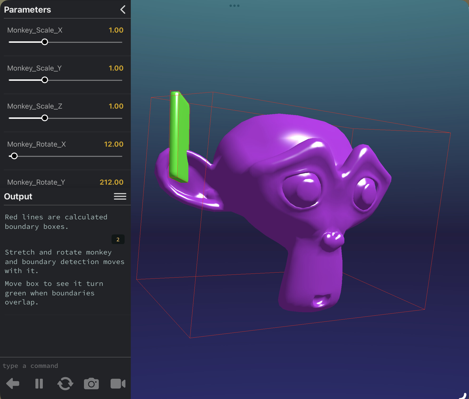
print("Red lines are calculated boundary boxes.\n\nStretch and rotate monkey and boundary detection moves with it.\n\nMove box to see it turn green when boundaries overlap.")
end
-- Parameters for controlling the monkey's transformation
function setupParameters()
parameter.number("Monkey Scale X", 0.1, 3, 1)
parameter.number("Monkey Scale Y", 0.1, 3, 1)
parameter.number("Monkey Scale Z", 0.1, 3, 1)
parameter.number("Monkey Rotate X", 0, 360, 12)
parameter.number("Monkey Rotate Y", 0, 360, 212)
parameter.number("Monkey Rotate Z", 0, 360, 0)
-- Parameters for controlling the box's position
parameter.number("Box Position X", -10, 10, 1.08)
parameter.number("Box Position Y", -10, 10, 0.61)
parameter.number("Box Position Z", -10, 10, -0.5)
end
function draw()
scene:update(DeltaTime)
scene:draw()
monkey.scale = vec3(Monkey_Scale_X, Monkey_Scale_Y, Monkey_Scale_Z)
monkey.rotation = quat.eulerAngles(Monkey_Rotate_X, Monkey_Rotate_Y, Monkey_Rotate_Z)
box.position = vec3(Box_Position_X, Box_Position_Y, Box_Position_Z)
-- Draw the absolute bounds of the monkey
drawAbsoluteBounds(monkey)
-- Draw the absolute bounds of the box
drawAbsoluteBounds(box)
-- Check if the test point is inside the bounding box
if absoluteBoundsIntersect(monkey, box) then
box.material.diffuse = color(0, 255, 0) -- Green if intersect
else
box.material.diffuse = color(255, 112, 0) -- Red if not
end
end
function getAbsoluteBounds(entity)
local b = entity.model.bounds
local corners = {
b.min,
vec3(b.min.x, b.min.y, b.max.z),
vec3(b.min.x, b.max.y, b.min.z),
vec3(b.min.x, b.max.y, b.max.z),
vec3(b.max.x, b.min.y, b.min.z),
vec3(b.max.x, b.min.y, b.max.z),
vec3(b.max.x, b.max.y, b.min.z),
b.max
}
local transformedCorners = {}
for _, corner in ipairs(corners) do
table.insert(transformedCorners, entity:transformPoint(corner))
end
return transformedCorners
end
function drawAbsoluteBounds(entity)
local transformedCorners = getAbsoluteBounds(entity)
-- Connect the transformed corners with lines
local lines = {
{1, 2}, {2, 4}, {4, 3}, {3, 1},
{5, 6}, {6, 8}, {8, 7}, {7, 5},
{1, 5}, {2, 6}, {3, 7}, {4, 8}
}
for _, line in ipairs(lines) do
scene.debug:line(transformedCorners[line[1]], transformedCorners[line[2]], color(255, 0, 0))
end
end
function pointIsInBounds(point, modelEntity)
-- Transform the point to the model's local space
local localPoint = modelEntity:inverseTransformPoint(point)
-- Get the model's original bounds
local bounds = modelEntity.model.bounds
return localPoint.x >= bounds.min.x and localPoint.x <= bounds.max.x and
localPoint.y >= bounds.min.y and localPoint.y <= bounds.max.y and
localPoint.z >= bounds.min.z and localPoint.z <= bounds.max.z
end
function absoluteBoundsIntersect(entityA, entityB)
local cornersA = getAbsoluteBounds(entityA)
local cornersB = getAbsoluteBounds(entityB)
-- Get normals for entityA
local normalsA = getBoxNormals(cornersA)
-- Get normals for entityB
local normalsB = getBoxNormals(cornersB)
-- Check for separation on each normal
for _, normal in ipairs(normalsA) do
if isSeparatedOnAxis(normal, cornersA, cornersB) then
return false
end
end
for _, normal in ipairs(normalsB) do
if isSeparatedOnAxis(normal, cornersA, cornersB) then
return false
end
end
return true
end
function getBoxNormals(corners)
return {
(corners[2] - corners[1]):normalize(),
(corners[4] - corners[1]):normalize(),
(corners[5] - corners[1]):normalize()
}
end
function isSeparatedOnAxis(axis, cornersA, cornersB)
local minA, maxA = projectToAxis(axis, cornersA)
local minB, maxB = projectToAxis(axis, cornersB)
return maxA < minB or maxB < minA
end
function projectToAxis(axis, corners)
local min = math.huge
local max = -math.huge
for _, corner in ipairs(corners) do
local projection = corner:dot(axis)
min = math.min(min, projection)
max = math.max(max, projection)
end
return min, max
end
…the stretching of the monkey model here makes this impossible to do with standard Craft physics, right?
…though I wonder if there’s a way to combine this with ignat’z approach, using something ChatGPT told me about called Separating Axes Theorem:
The Separating Axis Theorem (SAT) is a common method to detect intersections between two oriented bounding boxes, or OBBs. The basic idea is to project both boxes onto potential separating axes (in our case, the face normals of the boxes). If there’s any axis where the projections of the two boxes don’t overlap, then the boxes don’t intersect.
…now this is way past the boundaries of my math abilities, but could one theoretically use separate craft cameras to generate the kind of masks used in ignatz’s project, but from different angles?
…Then use those masks combined with Separating Axis Theorem to perform more pixel-accurate collision detection?
Basically:
- use the monkey-box method above to detect collisions of OBBs
- when an OBB collision occurs, create ignatz masks for each “face normal of the boxes”
- only report a collision if there’s no axis where the masks don’t overlap or touch
…is that possible in Codea in theory?
It must be fairly straightforward to calculate if a 3d line intersects with a 3d box. I see a few implementations when searching the web.
By the way, I notice the Codea models example uses an undocumented debug function to display the bounding boxes.
@piinthesky well exactly, it’s possible to calculate, but it seems to not be possible for Craft raycasting to do the calculating for us.
I did look at the Codea models example, but I think it’s less helpful than it might appear. As far as I can tell, it doesn’t actually display the boxes themselves, where they are, it displays their dimensions. You have to manually do the transformations that put it in the same location as the model.
That what it looks like is happening in the Codea models example, at least.
Plus it only gives you the original model dimensions, it won’t give you the dimensions adjusted by the entity’s current transformations. As far as I can tell.
Getting the bound is extremely helpful, for sure, but there’s a lot of lifting to be done after that—as far as I can tell. I have to remember that I can always be wrong about these things.
@piinthesky all that aside, do you have any inkling if Craft cameras could be used to combine @ignatz’s masking approach with Separating Axis Theorem to do precise collision detection without rigidbodies?
once you have the original bounding box, you could make a craft box with the same dimension and orientation. then just apply the same scaling and translation to that box as to the model.
i suppose once the scaling and translating are done. you coukd create a new craft box with rigid body with those dimensions and rotation and do a raycast to it.
All the stuff with shader and colours seems complicated.
SAT is apparently a known approach to collision detection.
The key is that @Ignatz’s thing makes it possible to get 2D silhouettes of Craft models from different angles, and all SAT does is check if those silhouettes are touching.
Combining @Ignatz’s solution with SAT is way above my head, because I understand neither of them, but there are certainly people who do, and for them it might be trivial.
Hi, UberGoober. I haven’t logged in here for 8 years and have forgotten all I knew - but I did keep the documents and notes I wrote.
This “book” of 3D techniques explains how my collision detection works. See page 35.
3D Bag of Tricks.pdf
Please don’t bother asking me questions, I truly don’t remember!
Good luck.
2 Likes